Daniels Audio Processor 43-911913
Updated 5 February 2025
I was looking for documentation describing the alignment procedure for this device, including the parts locator showing which pot is where. I found what I was looking for, buried amongst the many versions of the manuals I have for the VHF high-band MT-3 gear.
Attached here is a PDF of the three pages I found describing a 911910-002 audio processor board. It looks exactly like the 43-911913 board I have, at least in terms of the locations of the adjustment potentiometers on the board. I have tuned up the module I have, and the procedure seems to work.
Please note: some information is probably missing. The pages I have are numbered 2-30.7, 2-30.8, and 2-30.10. I suspect the missing page 2-30.9 contains detail about the Auxiliary Input Gain and Subtone 2 Input Level adjustments (R48 and R44, respectively), as they are not mentioned in the documentation I have. Still, what I have is enough to get the module "tuned up and running."
The information below describes the audio processor I have. I put it up here at this page in the hopes that someone would recognize it and help me with the documentation ... and then I was persuaded to dig through all of my Daniels MT-3 documentation, and I found the above mentioned (and linked) information. I am including the below information in case others are still looking for this information.
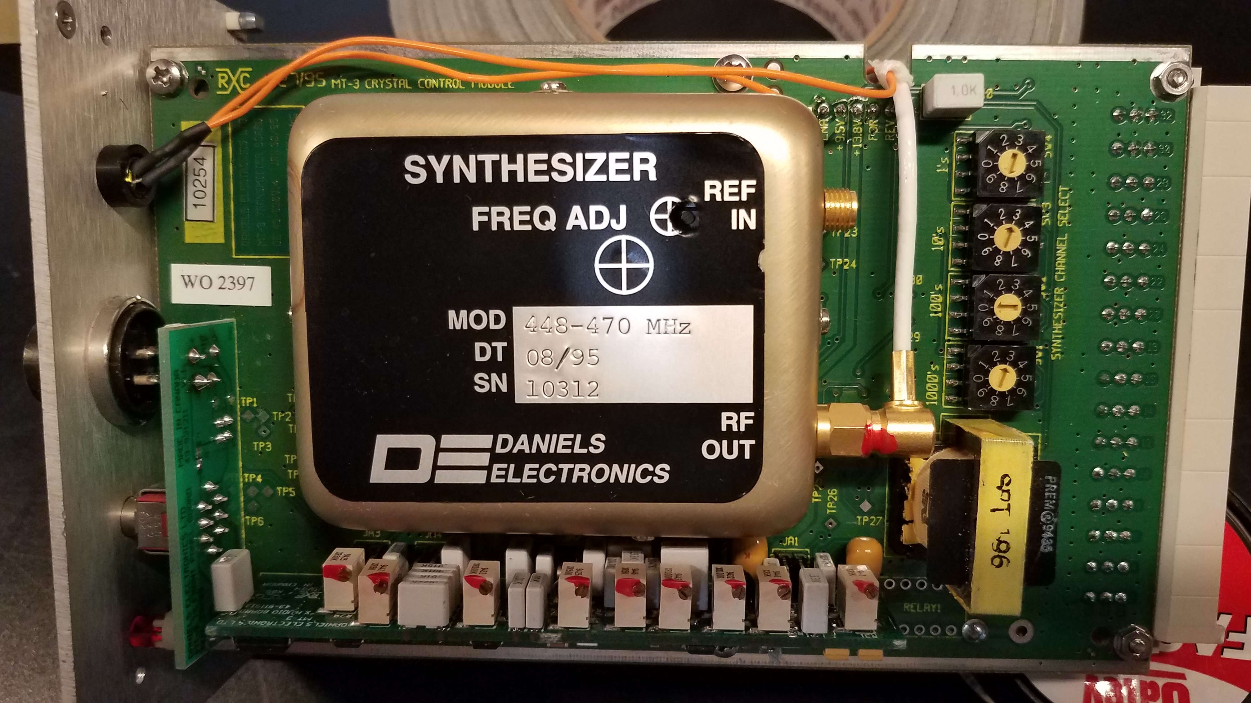
The assembly I have is in a UT-3/460-SWC800 Transmitter module, serial # 10254, manufacture date 8/95.
The images below will link you to the full size images if you click on them, for better viewing.

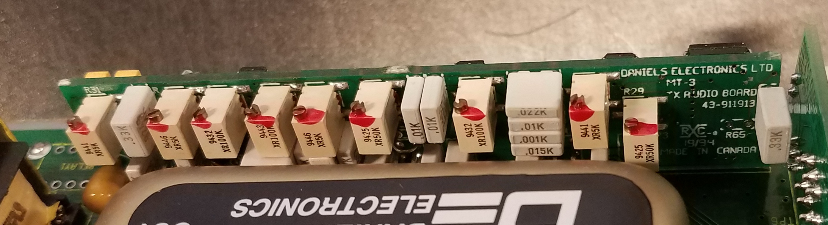
This is the board in question.
The arrangement of the adjustment potentiometers is somewhat unique on this board.
From the front panel (right side of the image), the pots are arranged in a 2-1-5-1 grouping.
The only pots I can identify easily are R31 (far left) and R-29 (far right).
I have not removed the oscillator module to inspect the audio processor board for silk screen detail.
From what I can see there isn't any relating to the adjustment pots.

Here is the transmitter main board, for reference.
I can now tell you that the potentiometers are in the order (from front panel to rear):
R29 R44 // R48 // R14 R42 R8 R38 R2 // R31
So the sequence as they appear in the image above matches the sequence in the line of text above.